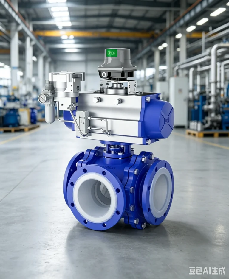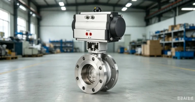
Slurry Valve Instruction Manual
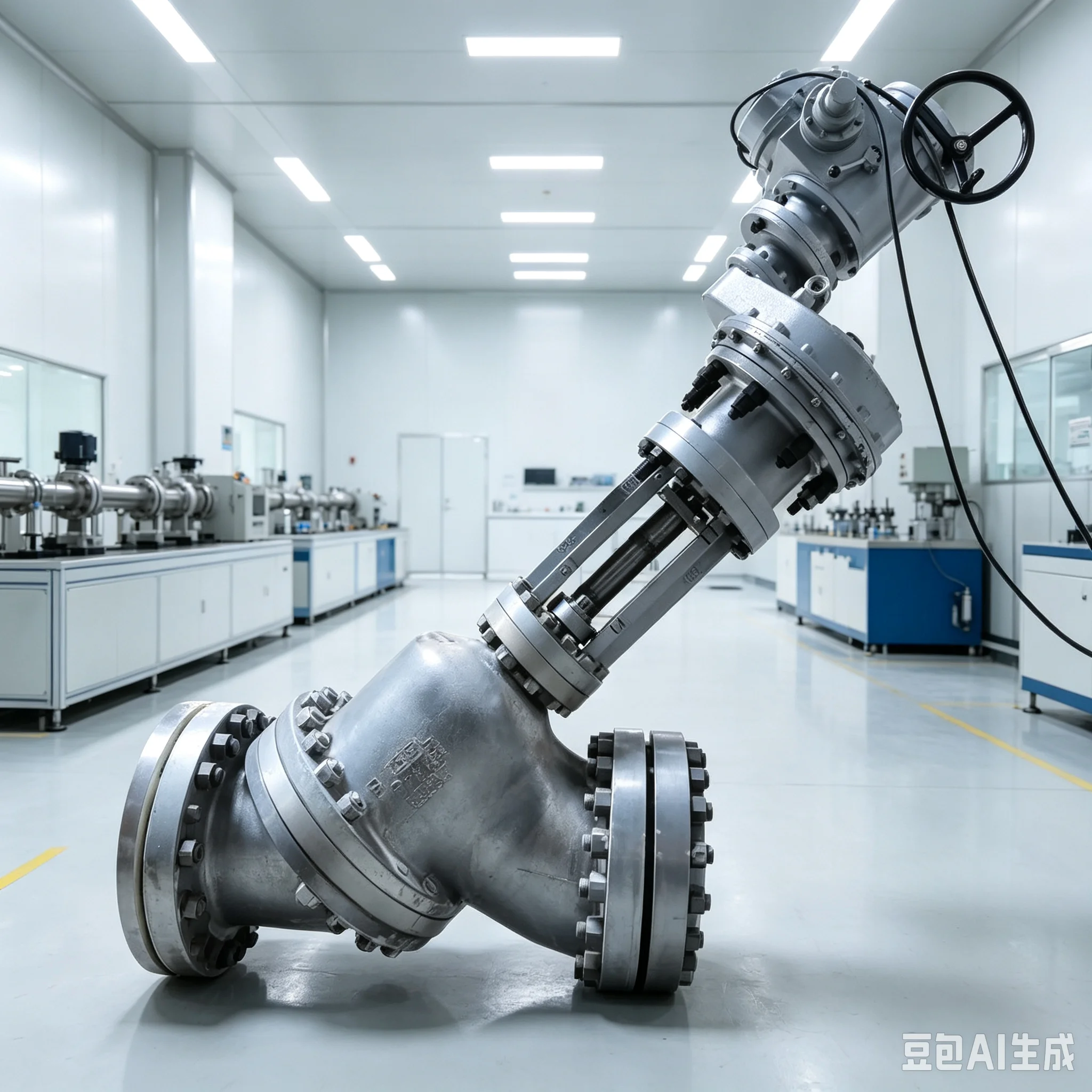
PRODUCT PARAMETERS
Description
Slurry Valve Instruction Manual
I. Product Overview
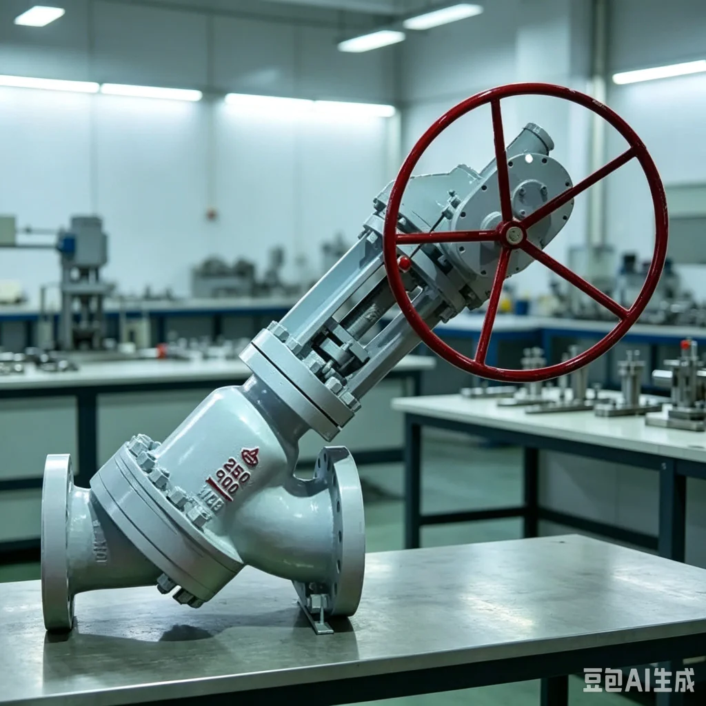
The slurry valve—also known as a slurry gate valve—is a specialized shut-off valve designed for media containing particles and impurities, or characterized by high viscosity and high abrasiveness. It is widely used in industries such as mining and metallurgy, alumina and chemical processing, wastewater treatment, power plant desulfurization, and the transport of construction material slurries. Featuring a straight-through flow path design with no dead zones, the valve offers minimal flow resistance and operates smoothly without jamming. It effectively prevents issues such as slurry sedimentation, clogging, and wear, ensuring reliable full-open/full-close shut-off control; however, it is not designed for flow regulation.
This product is designed and manufactured in strict accordance with national and industry standards such as GB/T 12235 and JB/T 13604-2018. Flange dimensions comply with GB/T 9113.1 and HG 20592 standards, while inspections and testing are conducted according to GB/T 26480 and API 598 specifications. Characterized by a compact structure, resistance to wear and corrosion, and excellent sealing performance, the valve is suitable for a wide range of demanding slurry transport applications. II. Model Designation and Structural Features
- Model Designation (Standard System)
Taking the common Z73X/Z373X slurry valve as an example:
Z: Gate valve category; 7: Wafer connection; 3: Rising stem, parallel gate; X: Soft rubber seal (TC for ceramic seal, Y for hard alloy seal);
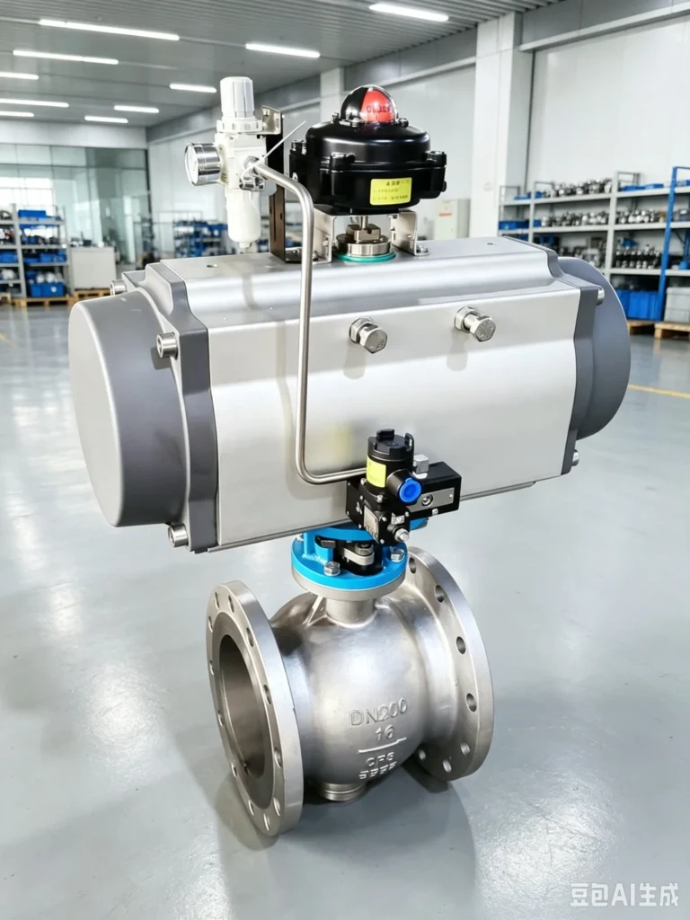
Actuation method: Manual (no code), worm gear (3), electric (9), pneumatic (6)
Nominal pressure: PN2.5–PN16 (high-pressure ratings of PN25–PN63 available upon request) - Key Structural Features
- Straight-through flow path with no dead zones; the bore matches the pipeline diameter, ensuring smooth medium flow, preventing slurry accumulation, and eliminating clogging issues;
- Gate and seat made of highly wear-resistant materials (options include cast iron, stainless steel, ceramic, and polyurethane lining); resistant to particle erosion and corrosion, ensuring a long service life;
- Compatible with both soft and hard sealing options; offers reliable sealing performance with zero leakage when fully closed; suitable for both dry and wet slurry media;
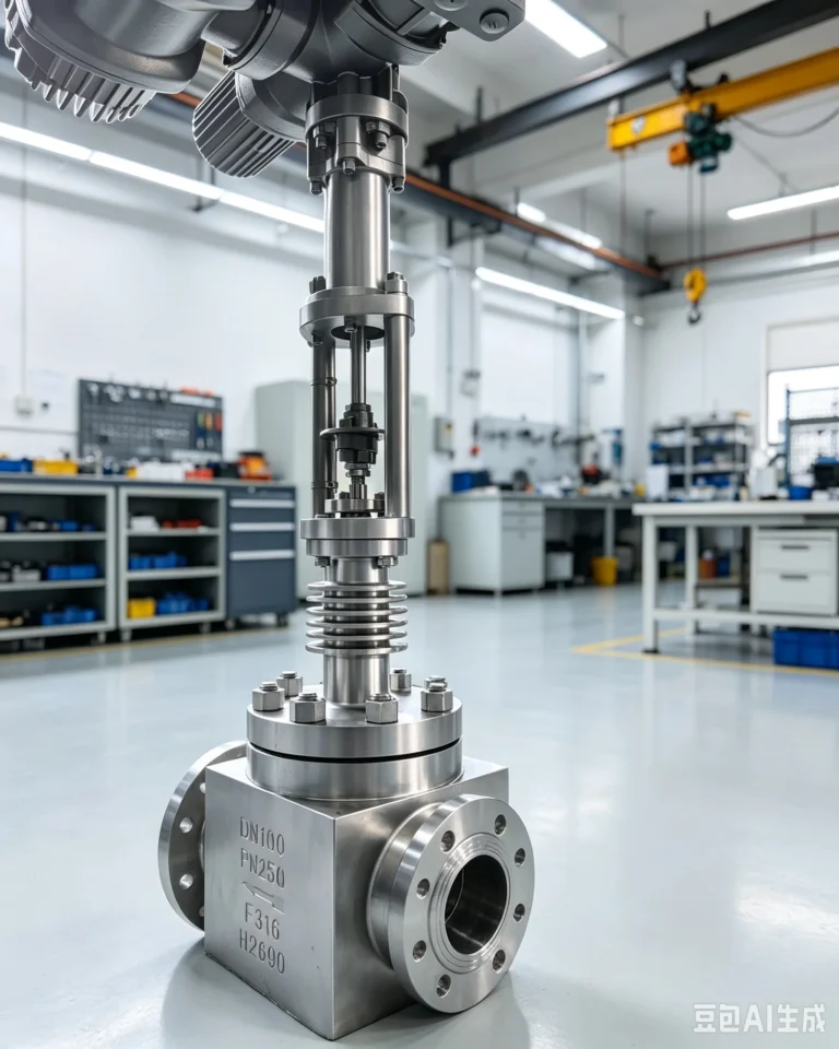
- Rising stem design allows for clear visibility of the valve stroke, enabling easy determination of the open/closed status and ensuring intuitive, convenient operation;
- Wafer or flanged connection options available; easy to install and suitable for various piping configurations; simple maintenance and disassembly. III. Key Technical Parameters
Item
Technical Parameters
Nominal Diameter
DN25–DN600
Nominal Pressure
PN2.5, PN6, PN10, PN16 (high-pressure models available upon request)
Applicable Media
Particle-laden fluids such as ore slurry, coal slurry, mud, lime slurry, alumina slurry, and sewage containing impurities
Medium Temperature
≤120°C (fluoroplastic or ceramic lining options available for high-temperature conditions up to 200°C)
Connection Type
Wafer, Flanged (RF – Raised Face)
Actuation Method
Manual, Worm gear, Electric, Pneumatic
Valve Body Material
Gray cast iron, Ductile iron, ZG25I, Stainless steel, Polyurethane lining, Ceramic lining
Sealing Material
Natural rubber, Nitrile rubber (NBR), PTFE, Ceramic, Hard alloy
Applicable Conditions
Pipelines transporting slurries that are particle-laden, highly abrasive, prone to sedimentation, or corrosive
IV. Installation Instructions - Pre-installation Inspection
- Verify that the valve model, specifications, and pressure rating meet the design requirements for the application; check compatibility regarding the medium, temperature, and pressure;
- Inspect the valve body, disc, and sealing surfaces for cracks, deformation, wear, or damage, and ensure all accessories are complete and in good condition;
- Clear the pipeline interior of debris, welding slag, silt, and particulate matter to prevent scratching the sealing surfaces or causing jamming after installation;
- Confirm that the pipeline flange faces are flat and undeformed, and that the pipeline alignment (coaxiality) meets installation requirements. 2. Installation Requirements
- The valve may be installed horizontally or vertically; the flow direction of the medium must align with the arrow marked on the valve body—reverse installation is strictly prohibited.
- For wafer-style valves, use dedicated bolts and tighten them evenly; ensure the pipe flanges at both ends are parallel and aligned to avoid uneven stress or crushing of the valve body.
- For flanged valves, install appropriate gaskets and tighten bolts evenly in a diagonal pattern to prevent leakage caused by uneven loading.
- After installing electrically or pneumatically actuated valves, calibrate the opening/closing travel and limit switches to ensure the valve reaches the full-open and full-closed positions without over-travel or binding.
- Do not use the valve stem or actuator to bear weight; do not forcibly pull or pry the valve, as this may cause structural deformation or damage.
- Post-Installation Pressure Testing
Upon completion of installation, conduct hydrostatic strength and sealing tests in accordance with national standards; the valve is deemed qualified only if it maintains pressure without leakage or pressure drop, at which point it may be put into service.
V. Operating Procedures - Manual/Worm Gear Operation
- Opening: Slowly rotate the handwheel/worm gear mechanism clockwise; the stem and valve plate will rise until the valve is fully open. Stop rotating once the limit is reached; do not force the mechanism further.
- Closing: Slowly rotate the handwheel/worm gear mechanism counter-clockwise; the stem and valve plate will descend until the plate seats firmly against the valve seat, achieving a complete seal and shutting off the medium flow.
- Perform all operations slowly and smoothly; abrupt opening or closing is prohibited to prevent damage to the sealing surfaces and valve plate caused by fluid shock. 2. Electric/Pneumatic Operation
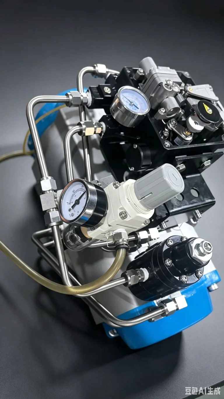
- Before startup, verify secure power and air supply connections, ensure pressure parameters meet equipment specifications, and confirm that limit switches and protective devices are functioning correctly.
- Operate opening and closing via the control panel or buttons; the equipment will stop automatically at the limits, requiring no manual intervention.
- If stalling, abnormal noise, or irregular startup/shutdown occurs during operation, immediately shut down and disconnect power and air supplies; resume operation only after troubleshooting.
- Operational Prohibitions
- Strictly prohibited for flow regulation; only fully open or fully closed states are permitted. Operation in a partially open state can cause high-speed erosion and wear on sealing surfaces.
- Disassembly of the valve or its components while the pipeline is pressurized or before the medium has been drained is prohibited.
- Operation exceeding nominal pressure or medium temperature limits is strictly prohibited.
VI. Maintenance and Servicing - Routine Maintenance
- Regularly clean debris and slurry residue from the valve body surface and stem to keep the valve clean and prevent impurity accumulation that could jam moving parts.
- Regularly check stem lubrication and apply specialized lubricant to ensure smooth opening and closing without sticking.
- Conduct daily inspections to check the valve seal and connection points for leaks, and ensure the actuator operates smoothly without abnormal noise.
- Periodic Maintenance (Every 3–6 Months)
- Disassemble and inspect the valve seat, seals, and valve plate for wear; replace them promptly if wear exceeds 5mm or if signs of aging, damage, or deformation appear.
- Check bolts and fasteners for looseness and tighten them in a diagonal pattern to prevent leaks caused by operational vibration.
- For electric valves, check the condition of the motor, limit switches, and terminals; for pneumatic valves, check the cylinder, seals, and air supply line integrity.
- Clear accumulated slurry from the flow passage to prevent jamming or poor sealing caused by long-term buildup. 3. Maintenance During Storage
- For long-term storage, leave the valve in the fully open position and drain the internal medium to prevent the slurry from drying, caking, or corroding the valve body.
- Apply anti-rust grease to exposed valve stems and cover them for protection against rust.
- Store in a dry, well-ventilated environment; avoid exposure to moisture, direct sunlight, or corrosive conditions. VII. Common Faults and Troubleshooting
Fault Symptom
Cause of Fault
Troubleshooting Method
Valve sticks or binds during opening/closing - Slurry deposits or particles jamming the valve plate; 2. Stem rusted or insufficiently lubricated; 3. Excessive misalignment during installation
- Drain medium and clear internal debris/clumps; 2. Clean stem and apply grease; 3. Re-align piping and valve installation position
Medium leakage after closing - Seal worn, aged, or damaged; 2. Particles/debris stuck in valve seat; 3. Valve not fully closed; 4. Loose flange bolts
- Replace with new seals; 2. Clean debris from sealing surfaces; 3. Operate again to ensure full closure; 4. Tighten flange bolts evenly in a diagonal pattern
Operation is stiff or requires excessive force - Stem lubrication failure; 2. Actuator malfunction (electric/pneumatic); 3. Parts rusted or deformed
- Replenish or replace lubricant; 2. Inspect actuator air/power supply and transmission components; 3. Repair or replace deformed/rusted parts
Actuator operates abnormally or fails to move - Power/air supply failure; 2. Limit switch damaged or misaligned; 3. Transmission mechanism detached or jammed
- Check power connection and adjust air supply pressure; 2. Calibrate or replace limit switch; 3. Repair and reset transmission mechanism
VIII. Packaging, Transportation, and Storage - Before leaving the factory, the product is cleaned and treated against rust; protective caps are fitted to sealing faces; the valve body is wrapped in protective material; and accessories are packaged separately to prevent damage from impact during transport;
- Handle with care during transport (load and unload gently); do not throw, strike, or subject to heavy pressure to avoid valve body deformation or damage to sealing surfaces;
- Store finished products in a dry, ventilated warehouse free from corrosive gases; stack flat and securely to prevent moisture-induced rust or contamination by debris. IX. Warranty Information
- This product is manufactured in strict accordance with national standards and has undergone rigorous factory inspections to ensure quality compliance.
- The warranty period is 12 months, subject to proper installation, use, and maintenance. Repairs or part replacements will be provided free of charge for quality issues not caused by human error during this period.
- Malfunctions resulting from improper installation, operation beyond specified parameters, human-induced damage, or unauthorized disassembly or modification are not covered by the warranty.
Note: Please contact the manufacturer if you require valves with custom materials, pressure ratings, or actuation types. Do not disassemble the equipment yourself in the event of a malfunction; it is recommended to contact professional technical personnel for inspection and repair.
FAQs
What types of products can we offer?
Make amazing 60 degree bevel cuts with our 8-1/4 in. SKILSAW Worm Drive model SPT78W-01. This saw is powered by our largest 15 amp Dual-Field high torque motor so you will make the last cut as precisely as you did the first cut. Exclusive 60 degree bevel. High torque Dual-Field motor. Legendary SKILSAW durability. Includes: SPT78W 8-1/4 In. Worm Drive SKILSAW, 24 Tooth Carbide blade and multi-functional blade wrench.

What logistics do we ship through?
Make amazing 60 degree bevel cuts with our 8-1/4 in. SKILSAW Worm Drive model SPT78W-01. This saw is powered by our largest 15 amp Dual-Field high torque motor so you will make the last cut as precisely as you did the first cut. Exclusive 60 degree bevel.




Can it be customized as per our requirements?

Make amazing 60-degree bevel cuts with our 8-1/4 in. SKIL Worm Drive Skilsaw model SPT78W-01. This Skilsaw is powered by our largest 15 amp Dual-Field™ high torque motor so you will make the last cut as precisely as you did the first cut. Exclusive 60-degree bevel. High torque Dual-Field™motor. Legendary SKIL durability.
What is our ordering process?
Shenguan is a direct seller of CATL, LISHEN, EVE, GOTION, Narada, TAFEL, CALB, REPT and other batteries. We have fresh stock, ready for shipment. Support ODM&OEM, please contact the store customer service to provide customized requirements.
What services are included in the after-sales service?
- This saw is powered by our largest 15 amp Dual-Field
- High torque motor so you will make the last cut as precisely as you did the first cut.
- Exclusive 60 degree bevel. High torque Dual-Field motor. Legendary SKILSAW durability.
- Includes: SPT78W 8-1/4 In. Worm Drive SKILSAW, 24 Tooth Carbide blade and multi-functional blade wrench.