Pneumatic Gate Valve Instruction Manual
Pneumatic Gate Valve Instruction Manual
I. Product Overview
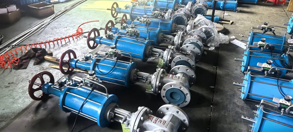
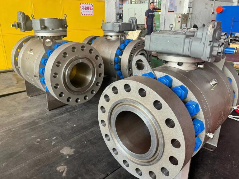
The pneumatic gate valve is an automated control valve that utilizes compressed air as its power source; a pneumatic actuator drives the gate up and down to control the flow of pipeline media. Featuring a straight-through flow path, the valve offers minimal flow resistance, smooth operation, and reliable sealing. It is designed for fully open or fully closed service and is not intended for throttling or flow regulation.
This product features a compact structure, rapid response, excellent explosion-proof performance, and a high degree of automation. It is compatible with water, steam, oil, gas, and mildly corrosive media, making it widely applicable to pipeline systems in industries such as petroleum, chemicals, electric power, metallurgy, municipal water supply and drainage, HVAC, and fire protection. The valve is designed, manufactured, and inspected in strict accordance with national and industry standards (such as GB/T12234, GB/T26480, and JB/T8857), ensuring stable performance, safety, and durability.
II. Model Designation and Structural Features
- Common Model Descriptions (Z641/Z645 Series)
Z: Gate Valve | 6: Pneumatic Actuation | 4: Flange Connection | 1: Rising Stem, Wedge-type Single Gate | 5: Non-rising Stem, Wedge-type Gate
Suffix Meanings: H – Hard Alloy Seal (high-temperature and wear-resistant); X – Soft Rubber Seal (zero leakage); F – PTFE Seal (corrosion-resistant); Y – Hard Alloy Seal - Key Structural Features
- Pneumatic Actuation: Utilizes double-acting or single-acting pneumatic actuators for rapid opening/closing and smooth operation; supports remote automated control and is suitable for use in explosion-proof environments.
- Excellent Sealing Performance: Metal hard seals withstand high temperatures, high pressures, and wear; soft seals ensure zero leakage, meeting requirements for clean media and low-pressure sealing applications.
- Unobstructed Flow Path: Straight-through bore design ensures the medium flows without resistance or stagnation; prevents slag accumulation and pipe clogging, making it suitable for long-term continuous operation. 2. Comprehensive protection: Features travel indication and travel-limiting structures; optional accessories include solenoid valves, air service units (FRL), limit switches, and manual override devices.
- High versatility: Compatible with clean, dry compressed air; operates with stable air supply pressure; easy to install and commission; low maintenance costs.
III. Main Technical Parameters
Parameter Item
Technical Specification
Nominal Diameter
DN15–DN600
Nominal Pressure
PN10, PN16, PN25, PN40
Applicable Media
Water, steam, air, oil, gas, weak acids/alkalis
Medium Temperature
-20°C to 425°C (depending on seal material)
Air Supply Pressure
0.4–0.6 MPa
Connection Type
Flanged, wafer-style
Valve Body Material
Cast iron, ductile iron, carbon steel, stainless steel
Actuation Method
Pneumatic (manual override available)
Control Method
On/off type; compatible with solenoid valves, signal feedback, and explosion-proof components
Leakage Class
Soft seal: Class VI (zero leakage); Hard seal: Class IV
IV. Pre-installation Inspection and Preparation - Verify that the valve model, pressure rating, diameter, material, and operating temperature match the on-site operating conditions.
- Inspect the valve body, stem, and sealing surfaces for cracks, deformation, dents, or damage; ensure the pneumatic actuator is intact.
- Clean the pipeline interior to remove welding slag, rust, and debris, preventing scratches to sealing surfaces, jamming, or internal leakage.
- Check that pipeline flange faces are flat and concentrically aligned; ensure there is no forced alignment, misalignment, or tilting.
- Confirm that the on-site compressed air supply is clean, dry, and stable; ensure an air service unit (filter, regulator, lubricator) is installed. V. Installation Specifications
- The valve may be installed horizontally or vertically; the flow direction indicated on the valve body must align with the pipeline flow direction. Reverse installation is prohibited.
- Install certified gaskets during flange installation. Tighten bolts evenly in a diagonal pattern and in multiple stages to prevent valve body deformation or leakage caused by uneven loading.
- Ensure pneumatic pipeline connections are secure and reliably sealed, with no air leaks or loose fittings. Route solenoid valves and signal lines neatly; strictly adhere to explosion-proof regulations in hazardous areas.
- After installation, ensure the valve body is not subjected to external forces, tension, or torque from the piping to avoid valve body deformation or actuator damage.
- For valves equipped with a manual override mechanism, verify that the manual/pneumatic switching mechanism is set to the pneumatic operating position before installation.
VI. Commissioning and Operating Instructions - Commissioning
- Supply clean compressed air and adjust the air supply pressure to 0.4–0.6 MPa; check the pneumatic circuit for leaks.
- Cycle the valve (open/close) 3–5 times without load to confirm smooth operation, absence of sticking or abnormal noise, and accurate travel and position indication.
- Conduct a pressure test with water or air; the valve is considered qualified if there is no external leakage at the valve body, flanges, or packing, and no internal leakage in the closed position.
- Normal Pneumatic Operation
- Valve Opening: The solenoid valve receives air/power, activating the pneumatic actuator; the valve stem rises, lifting the gate to fully open the valve, and the equipment sends an “open-position” feedback signal.
- Valve Closing: The solenoid valve loses air/power and switches state; the actuator resets, driving the gate downward to seal against the seat, fully closing the valve, and the equipment sends a “closed-position” feedback signal.
- Maintain stable air supply pressure during operation; avoid operating conditions involving overpressure or severe negative pressure fluctuations. 3. Manual Emergency Operation (for models equipped with this feature)
In the event of an air supply interruption, equipment maintenance, or power failure, the valve can be switched to manual mode: disengage the pneumatic self-locking mechanism and rotate the manual handwheel to open or close the valve. After operation, restore the valve to pneumatic operating mode to ensure normal automatic control.
- Operational Prohibitions
- The pneumatic gate valve is intended solely for shut-off service; throttling (operating in a partially open position) is strictly prohibited. Prolonged partial opening causes erosion of the sealing surfaces, leading to permanent damage and internal leakage.
- Do not disassemble the valve or actuator, or loosen flange bolts, while the pipeline is under pressure.
- Do not operate the valve beyond its rated nominal pressure or medium temperature limits.
VII. Maintenance and Servicing
- Routine Maintenance
- Keep the air supply clean and dry; regularly drain accumulated water and debris from the air filter-regulator-lubricator (FRL) unit to prevent moisture and impurities from entering the cylinder.
- Inspect air connections and the cylinder for air leaks, abnormal noises, or vibration.
- Check the valve body, flanges, and stuffing box for leakage; verify that the travel indicator and signal feedback are functioning correctly.
- Periodic Maintenance (Every 3–6 months)
- Apply lubricant to the valve stem and transmission components to ensure smooth opening and closing without binding.
- Inspect the sealing surfaces and gate for wear; promptly replace seals showing signs of aging, deformation, or severe wear.
- Tighten mounting bolts for the flange, bracket, and actuator to prevent loosening caused by vibration.
- Verify the operational reliability of limit switches and solenoid valves to ensure accurate signal feedback.
- Maintenance for Long-Term Decommissioning
- Drain the medium from the pipeline and valve body; keep the valve body clean and dry.
- Leave the valve in the fully open or fully closed position to prevent fatigue caused by prolonged pressure on the sealing surfaces.
- Disconnect the air and power supplies, apply anti-rust grease to exposed valve stems, and store the valve in a dry, well-ventilated environment. VIII. Common Faults and Troubleshooting
Fault Symptom
Cause of Fault
Troubleshooting Method
Valve fails to operate; no response to opening/closing commands
- Insufficient air supply pressure or air supply failure; 2. Solenoid valve malfunction or failure to switch; 3. Air line blockage or leakage; 4. Actuator cylinder damage
- Adjust air supply pressure to standard value; 2. Repair or replace solenoid valve; 3. Clear pipeline, tighten connections; 4. Repair or replace cylinder assembly
Valve operation is jerky or sluggish - Air supply contains water or impurities; 2. Lack of lubrication in moving parts; 3. Obstruction due to debris accumulation in valve body; 4. Limit switch interference
- Clean air treatment unit (FRL), dry the air supply; 2. Apply lubricant; 3. Remove debris from inside the valve body; 4. Re-calibrate travel limits
Incomplete closure; internal medium leakage - Sealing surface worn, aged, or damaged; 2. Impurities stuck on sealing surface; 3. Travel stroke incomplete; 4. Valve seat deformation
- Replace seals; 2. Clean debris from valve cavity; 3. Re-adjust opening/closing stroke; 4. Repair or replace valve body assembly
Air line leakage; cylinder air bypass - Loose air line fittings; 2. Cylinder seal aged or damaged; 3. Solenoid valve seal failure
- Tighten pipeline fittings; 2. Replace cylinder seals; 3. Repair or replace solenoid valve
Abnormal signal feedback - Limit switch misaligned or damaged; 2. Poor electrical contact; 3. Travel stroke incomplete
- Calibrate or replace limit switch; 2. Check and tighten wiring connections; 3. Re-adjust valve stroke
IX. Transportation, Packaging, and Storage
- Products are sealed and protected before leaving the factory; dust caps are installed on flange openings; the valve body is wrapped in anti-rust packaging; and accessories are individually packaged. • During transport, strictly avoid throwing, impact, or heavy pressure to prevent valve body deformation, actuator damage, or scratching of sealing surfaces.
- Store finished products in a dry, well-ventilated indoor environment free from corrosive gases; stack them neatly and protect against moisture and dust.
X. Warranty Information - This product is manufactured and inspected in strict accordance with national industry standards, with a 100% factory pass rate.
- The product carries a 12-month warranty, provided it is installed correctly, operated properly, and maintained regularly.
- During the warranty period, the manufacturer will provide free repairs or replacement parts for quality issues not caused by human error or improper operating conditions.
- Failures resulting from unauthorized modification, improper installation, operation beyond pressure or temperature limits, or accidental impact/damage are not covered by the warranty.
Important Note: In the event of equipment failure, do not attempt to disassemble the pneumatic actuator or sealing components yourself. Please contact the manufacturer’s professional technical staff for repairs, replacement parts, or products customized for special operating conditions.